Contents
Latency Simulator
Introduction
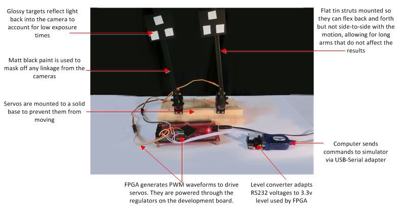
The mechanical latency simulator was designed to emulate the visual stimuli the techniques above would expect, by oscillating two arms at a number of frequencies and latencies. The mechanical simulator was designed to be simple to build, and sourced from easy to find components. The following section describes how the simulator is constructed and makes available its schematics and source code.
Operation
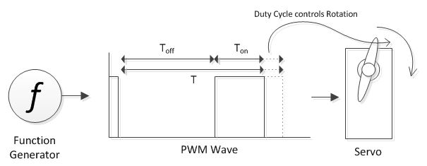
The simulator consists of two servos driven by a PWM waveform from an FPGA. The servos are HS-303 RC servos, which, like most other RC servos, are driven by a 50Hz PWM wave. A PWM wave is a rectangular waveform with a set frequency that encodes information by varying the duty-cycle (Ton / Toff. In the case of a servo, the duty cycle controls the angular position of the shaft. Typically, RC servos receive a PWM wave running at 50Hz (50 position samples per second) with the Ton period between 1500-2000us.
To introduce latency into one of the arms, the PWM waveform to it is delayed. This is done by sampling the waveform at 256KHz and loading the results into a buffer. An ideal PWM cycles between 0 and 1 so only one bit is required to store one sample. The sample rate depends on how much quantisation noise is tolerable. As described above, the angular offset of a servo's shaft is controlled by the duty cycle of the waveform supplied to it. The servos angular resolution cannot be infinite however. At some point, a change in duty cycle will fail to effect a change in angular position. The period of this change is known as the dead band, and the quantisation noise needs only to remain within this. For the HS-303 the dead band is ~us, so a sampling rate of 256KHz (period 8us) is sufficient.
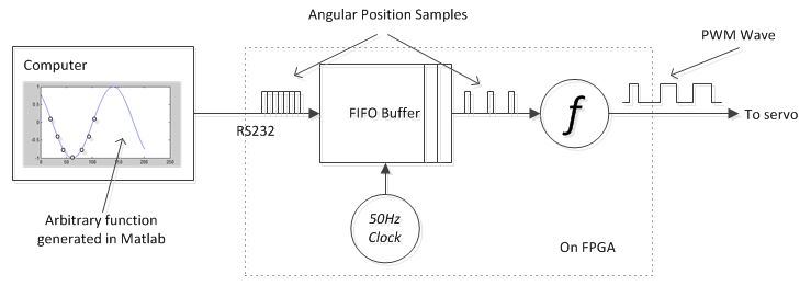
The buffer was designed with a depth of 256000, allowing up to a 1s delay. The source of the second arm is an offset into this buffer. This allows the latency to be programmable between 0 and 1s, and since the buffer is always filled to the end, even if its sampled before then, the latency can be set to any value instantaneously. The delay is loaded from the computer via the same serial link as before. The computer can provide a set of delays to simulate increasing or decreasing latency over time. These are clocked out again at 50Hz.
Delay or position samples are routed to the correct buffer by prefixing them with command words. Logic in the FPGA detects these command words, which as well as select the destination buffer, allow the computer to start and stop the sampling of position, delay or the servos themselves.
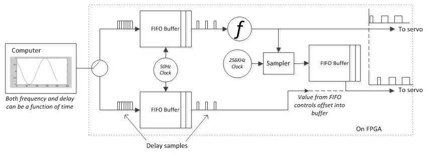
Both delay and angular position are linearly proportional to the values sent by the computer, they are scaled within the FPGA so that the full range of desirable angles and delays can fit within one byte. Controlling the servo is done through method calls to a Matlab object which opens a serial connection to the FPGA board and uses command words to control it. This object can be integrated into other Matlab programs by the user.
Downloads
The FPGA design and Matlab program to control it are available here.