 Picture: YC_arrangement.ps
Devices that encode and decode as well compress and decompress are called CODECs or CODer DECoders. Sometimes, these terms are used for audio, but mainly they are for video devices.
A video CODEC can be anything from the simplest A2D device, through to something that does picture pre-processing, and even has network adapters build into it (i.e. a videophone!). A CODEC usually does most of its work in hardware, but there is no reason not to implement everything (except the a2d capture:-), in software on a reasonably fast processor.
The most expensive and complex component of a CODEC is the compression/decompression part. There are a number of international standards, as well as any number of proprietary compression techniques for video.
Video compression
Video compression can take away the requirement for the very high data rates and move video transmission and storage into a very similar regime to that for audio. In fact, in terms of tolerance for poor quality, it seems humans are better at adapting to poor visual information than poor audio information. A simple minded calculation shows:
1024 x 1024 pixels,
3 bytes per pixel (24 bit RGB)
25 Frames per second
yields 75Mbytes/second, or 600Mbps - this is right on the limit of modern transmission capacity.
Even in this age of deregulation and cheaper telecoms, and larger, faster disks, this is profligate.
On the other hand, for a scene with a human face in, as few as 64 pixels square, and 10 frames per second might suffice for a meaningful image.
64x 64 pixels
3 bytes per pixel (24 bit RGB)
10 Frames per second
yields 122KBytes/Second, or just under 1 Mbps - this is achievable on modern LANs and high speed WANs but still not friendly!
Notice that in the last simple example, we did two things to the picture.
1. We used less "space" for each frame by sending less "detail".
2. We sent frames less frequently since little is moving.
1024 x 1024 pixels,
3 bytes per pixel (24 bit RGB)
25 Frames per second
yields 75Mbytes/second, or 600Mbps!!!
1. We could use less "space" for each frame by sending less "detail".
2. We could send frames less frequently since little is moving.
Lossy versus Lossless Compression
If a frame contains a lot of image that is the same, maybe we can encode this with less bits without losing any information (run length encode, use logically larger pixels etc. etc.). On the other hand, we can take advantage of other features of natural scenes to reduce the amount of bits - for example, nature is very fractal, or self-similar:- there are lots of features, sky, grass, lines on face etc., that are repetitive at any level of detail. If we leave out some levels of detail, the eye (and human visual cortex processing) end up being fooled a lot of the time.
Lossy versus Lossless Compression
Hierarchical coding is based on the idea that coding will be in the form of quality hierarchy where the lowest layer of hierarchy contains the minimum information for intelligibility. Succeeding layers of the hierarchy adds increasing quality to the scheme.
This compression mechanism is ideal for transmission over packet switched networks where the network resources are shared between many traffic streams and delays, losses and errors are expected.
Packets will carry data from only one layer, accordingly packets can be marked according to their importance for intelligibility for the end-user. The network would use these information as a measure of what sort of packets to be dropped, delayed and what should take priority. It should be noted that priority bits already exist in some protocols such as the IP protocol.
Hierarchical coding will also be ideal to deal with multicasting transmission over links with different bandwidths. To deal with such problem in a non-hierarchical encoding scheme, either the whole multicasting traffic adapts to the lowest bandwidth link capabilities thus degrading the video/audio quality where it could have been better or causing the low link to suffer from congestion and thus sites affected will lose some of the intelligibility in their received video/audio. With hierarchical coding, low level packets can be filtered out whenever a low bandwidth link is encountered thus preserving the intelligibility of the video/audio for the sites affected by these links and still delivering a better quality to sites with higher bandwidth.
Schemes that are now in relatively commonplace use include H.261 for videotelephony, MPEG for digital TV and VCRs and JPEG for still images. Most current standards are based on one simple technique, so first lets look at that.
The JPEG standard`s goal has been to develop a method for continuous-tone image compression for both color and greyscale images. The standard define four modes:
JPEG uses the Discrete Cosine Transform to compress spatial redundancy within an image in all of its modes apart from the lossless one where a predictive method issued instead.
As JPEG was essentially designed for the compression of still images, it makes no use of temporal redundancy which is a very important element in most video compression schemes. Thus, despite the availability of real-time JPEG video compression hardware, its use will be quite limit due to its poor video quality.
H261 is the most widely used international video compression standard for video conferencing. The standard describes the video coding and decoding methods for the moving picture component of a audiovisual service at the rates of p * 64 kbps where p is in the range of 1 to 30. The standard targets and is really suitable for applications using circuit switched networks as their transmission channels. This is understandable as ISDN with both basic and primary rate access was the communication channel considered within the framework of the standard.
H.261 is usually used in conjunction with other control and framing standards such as H221, H230 H242 and H320, of which more later.
The source coder operates on only non-interlaced pictures. Pictures are coded as luminance and two color difference components(Y, Cb, Cr). The Cb and Cr matrices are half the size of the Y matrix.
H261 supports two image resolutions, QCIF which is (144x176 pixels)and , optionally, CIF which is(288x352).
Picture: YC_arrangement.ps
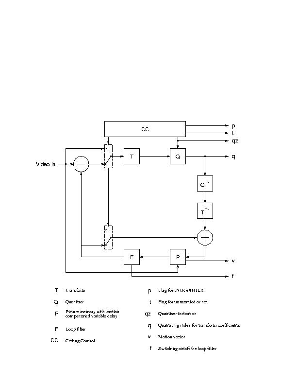
There main elements in an H.261 encoder are
 :h261-encoder.ps
H261 defines two types of coding. INTRA coding where blocks of 8x8 pixels each are encoded only with reference to themselves and are sent directly to the block transformation process. On the other hand INTER coding frames are encoded with respect to another reference frame.
A prediction error is calculated between a 16x16 pixel region (macroblock) and the (recovered) correspondent macroblock in the previous frame. Prediction error of transmitted blocks (criteria of transmission is not standardized) are then sent to the block transformation process.
.
H261 supports motion compensation in the encoder as an option. In motion compensation a search area is constructed in the previous (recovered) frame to determine the best reference macroblock . Both the prediction error as well as the motion vectors specifying the value and direction of displacement between the encoded macroblock and the chosen reference are sent. The search area as well as how to compute the motion vectors are not subject to standardization. Both horizontal and vertical components of the vectors must have integer values in the range + 15 and 15 though
In block transformation, INTRA coded frames as well as prediction errors will be composed into 8x8 blocks. Each block will be processed by a two-dimensional FDCT function.
H.261 Quantization & Entropy Coding
The purpose of this step is to achieve further compression by representing the DCT coefficients with no greater precision than is necessary to achieve the required quality. The number of quantizers are 1 for the INTRA dc coefficients and 31 for all others.
Entropy coding involves extra compression (non-lossy) is done by assigning shorter code-words to frequent events and longer code-words to less frequent events. Huffman coding is usually used to implement this step.
The video multiplexer structures the compressed data into a hierarchical bitstream that can be universally interpreted.
The hierarchy has four layers :
H.261 Error Correction Framing
An error correction framing structure is described in the H261 standard. The frame structure is shown in the figure. The BCH(511,493) parity is used to protect the bit stream transmitted over ISDN and is optional to the decoder. The fill bit indicator allows data padding thus ensuring the transmission on every valid clock cycle
H.261 Error Correction and Framing
 Picture: h261-fec.ps
Picture: H221.ps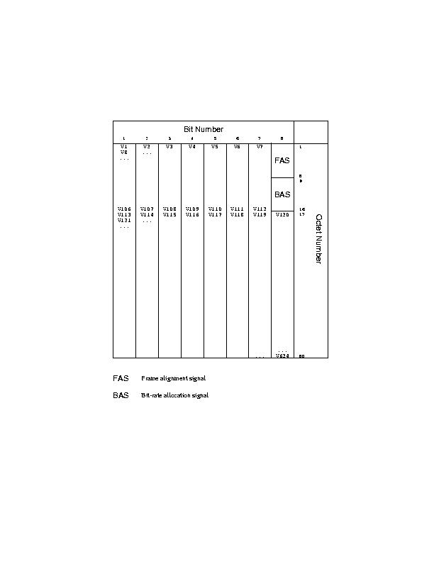
Picture: H221_framing.ps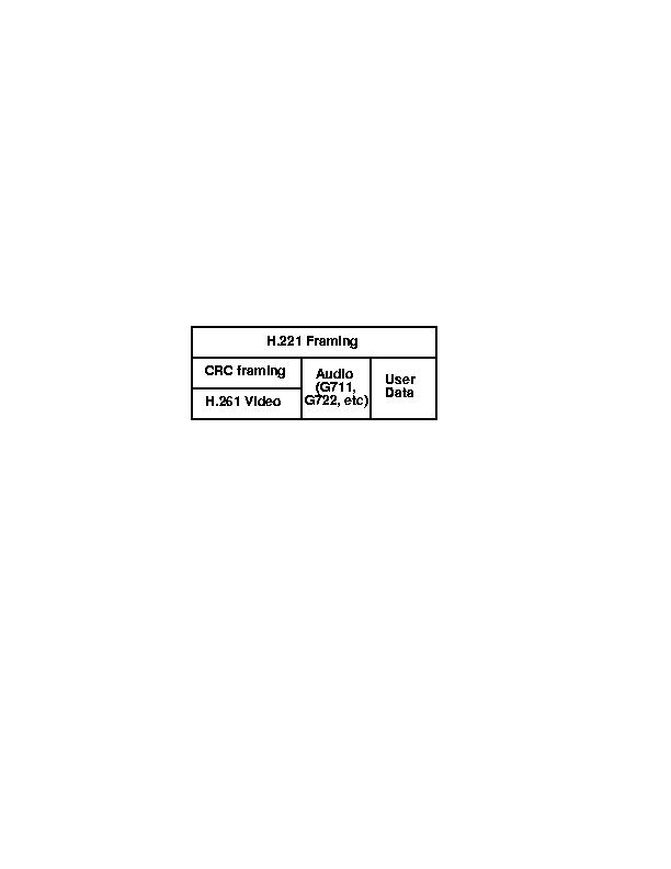
Though H261 as mentioned before can be considered the most widely video compression standard used in the field of multimedia conferencing, it has its limitations as far as its suitability for transmission over PSDN. H261 does not map naturally onto hierarchical coding. A few suggestions has been made as to how this can happen but as a standard there is no support of that. H261 resolution is fine for conferencing applications. Once more quality critical video data need to be compressed, the upper limit optional CIF resolution can start showing inadequate.
The aim of the MPEG-II video compression standard is to cater for the growing need of generic coding methods for moving images for various applications such as digital storage and communication. So unlike the H261 standard who was specifically designed for the compression of moving images for video conferencing systems at p * 64kbps , MPEG is considering a wider scope of applications.
The source pictures consist of three rectangular matrices of integers: a luminance matrix (Y) and two chrominance matrices (Cb and Cr).
The MPEG supports three format :
The output of the decoding process, for interlaced sequences, consists of a series of fields that are separated in time by a field period. The two fields of a frame may be coded independently (field-pictures) or can be coded together as a frame (frame pictures).
The diagram shows the intra, predictive and bi-directional frames that MPEG supports:
 : mpeg.ps
An MPEG source encoder will consist of the following elements:
1. Intrapictures (I-pictures)
These pictures are encoded only with respect to themselves. Here each picture is composed onto blocks of 8x8 pixels each that are encoded only with respect to themselves and are sent directly to the block transformation process.
2. Predictive pictures (P-pictures)
These are pictures encoded using motion compensated prediction from a past I-picture or P-picture. A prediction error is calculated between a 16x16 pixels region (macroblock) in the current picture and the past reference I or P picture. A motion vector is also calculated to determine the value and direction of the prediction. For progressive sequences and interlaced sequences with frame-coding only one motion vector will be calculated for the P-pictures. For interlace sequences with field-coding two motion vectors will be calculated. The prediction error is then composed to 8x8 pixels blocks and sent to the block transformation
3. Bi-directional pictures (B-pictures)
These are pictures encoded using motion compensates predictions from a past and/or future I-picture or P-picture. A prediction error is calculated between a 16x16 pixels region in the current picture and the past as well as future reference I-picture or P-picture. Two motion vectors are calculated. One to determine the value and direction of the forward prediction the other to determine the value and direction of the backward prediction. For field-coding pictures in interlaced sequences four motion vectors will thus be calculated.
It must be noted that a B-picture can never be used as a prediction picture.
The method of calculating the motion vectors as well as the search area for the best predictor is left to be determined by the encoder.
This is optional in MPEG II. This corresponds to a series of pictures. The first picture in the coded bitstream has to be an I picture. Group of pictures does assist random access. They can also be used at scenes cuts or other cases where motion compensation is ineffective. Applications requiring random access, fast-forwarder fast-reverse playback may use relatively short group of pictures.
This would correspond to one picture in the video sequence. For field pictures in interlaced sequences, the interlaced picture will be represented by two separate pictures in the coded stream. They will be encoded in the same order that shall occur at the output of the decoder.
This corresponds to a group of Macroblocks. The actual number of Macroblocks within a slice is not subject to standardization. Slices do not have to cover the whole picture. Its a requirement that if the picture was used subsequently for predictions, then predictions shall only be made from those regions of the picture that were enclosed in slices.
The structure of the MPEG bitstream is a tad more complex than that of H.261:
It must be noted that in MPEG the order of the picture in the coded stream is the order in which the decoder process them. The reconstructed frames are not necessarily in the correct form of display. The following example shows such a case
At the encoder input,
12 3 4 5 6 78 9 10 11 12 13
IB B P B B PB B I B B P
At the encoder output, in the coded bitstream and at the decoder input,
14 2 3 7 5 610 8 9 13 11 12
IP B B P B BI B B P B B
At the decoder output:
12 3 4 5 6 78 9 10 11 12 13
The scalability tools specified by MPEG II are designed to support applications beyond that supported by single layer video. In a scaleable video coding, it is assumed that given an encoded bitstream, decoders of various complexities can decode and display appropriate reproductions of coded video. The basic scalability tools offered are: data partitioning, SNR scalability, spatial scalability and temporal scalability. Combinations of these basic scalability tools are also supported and are referred to as hybrid scalability. In the case of basic scalability, two layers of video referred to as the lower layer and the enhancement layer are allowed. Whereas in hybrid scalability up to three layers are supported.
Profiles and levels provide a means of defining subsets of the syntax and semantics and thereby the decoder capabilities to decode a certain stream. A profile is a defined sub-set of the entire bitstream syntax that is defined by MPEG II. A level is a defined set of constraints imposed on parameters in the bit stream.
Five profiles are defined :
Along with four levels
Picture: h261vmpegsize.ps
MPEG II is now an ISO standard. Due to the forward and backward temporal compression used by MPEG, a better compression and better quality can be produced. As MPEG does not limit the picture resolution, high resolution data can still be compressed using MPEG. The scaleable extensions defined by MPEG can map neatly on the hierarchical scheme explained in 2.1. The out-of- order processing which occurs in both encoding and decoding side can introduce considerable latencies. This is undesirable in video telephony and video conferencing.
Prices for hardware MPEG encoders are quite expensive at the moment though this should change over the near future. The new SunVideo board (see below) does support MPEG I encoding. Software implementation of MPEG I DECoders are already available.
MPEG III was going to be a higher quality encoding for HDTV. It transpired after some studies that MPEG II at higher rates is pretty good, and so MPEG III has been dropped.
MPEG IV is aimed at the opposite extreme - that of low bandwidth or low storage capacity environments (e.g. PDAs). It is based around model-based image coding schemes (i.e. knowing what is in the picture!). It is aimed at UP TO 64kbps.
Subband coding is given as an example of an encoding algorithm that can neatly map onto hierarchical coding. There are other examples of hierarchical encoding none of them is a standard or widely used as the international standards such as H261 and MPEG.
Subband coding is based on the fact that the low spatial frequencies components of a picture do carry most of the information within the picture. The picture can thus be divided into its spatial frequencies components and then the coefficients are quantized describing the image band according to their importance; lower frequencies being more important. The most obvious mapping is to allocate each subband (frequency) to one of the hierarchy layers. If inter-frame coding is used, it has to be adjusted as not to create any upward dependencies.
Intel’s Digital Video Interactive compression scheme is based on the region encoding technique. Each picture is divided into regions which in turn is split into subregions and so on, until the regions can be mapped onto basic shapes to fit the required bandwidth and quality. The chosen shapes can be reproduced well at the decoder. The data sent is a description of the region tree and of the shapes at the leaves. This is an asymmetric coding, which requires large amount of processing for the encoding and less for the decoding.
DVI ,though not a standard, started to play an important role in the market. SUN prototype DIME board used DVI compression and it was planned to be incorporated in the new generation of SUN videopix cards.
This turned out to be untrue. Intel canceled the development of the V3 DVI chips. SUN next generation of VideoPix, the SunVideo card does not support DVI. The future of DVI is all in doubt.
CellB image compression is introduced by SUN and is supported by its new SunVideo cards. CellB is based on the techniques of block truncation and vector quantization.
In vector quantization, the picture is divided into blocks and the coefficients describing the blocks are used as vectors. As the vector space in which the block vectors exist would not be evenly populated by the blocks, the vector space can be divided into subspaces selected to provide equal probability of a random vector being in any of the subspaces. A prototype vector will be then used to represent all blocks whose vectors fall into a certain subspace.
The most processor intensive part of vector quantization is the generation of the codebook, that is the division of the vector space into subspaces. Then a copy of the codebook is sent to the other end. The image is then divided into blocks which is represented by the vector in the codebook that is closest to it and the label is sent. Decoding is done by looking up the labels in the code book and use the correspondent vector to represent the block.
CellB uses two fixed codebooks. It takes 3-band YUV images as input, the width and height must be dividable by 4. The video is broken into cells of 16 pixels each arranged in 4x4 group. The 16 pixels in a cell are represented by a 16-bit mask and two intensities or colors. These values specify which intensity to place at each of the pixel positions. The mask and intensities
can be chosen to maintain certain statistics of the cell, or they can be chosen to reduce contouring in a manner similar to ordered dither. This method is called Block Truncation Coding. It takes advantage of the primitives already implemented in graphics accelerators to provide video decoding.
See the diagram
Picture:vq-tree.ps
QuickTime and Video for Windows
Apple and Microsoft have both defined standards for their respective systems to accommodate video. However, in both cases, they are more concerned with defining a usable API so that program developers can generate applications that interwork quickly and effectively. Thus, Video for Windows and QuickTIme both specify the ways that video can be displayed and processed within the framework of the GUI systems on MS-Windows and Apple systems. However, neither specifies a specific video encoding. Rather, they assume that all kinds of encodings will be available through hardware CODECs or through software and thus they provide meta-systems that allow the programmer to name the encoding, and provide translations.