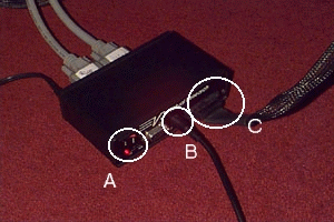
Figure 1: Helmet Control Box (front view).

The on/off switch is labelled A. The led below should come on when the unit is on. The video connection to the helmet is labelled C. Connection B is not necessary - it is composite video out that can be connected to a TV. This can be plugged into the front of the TV on the PV200, into the socket labelled AV4. Note the colour signal is corrupt or not present since only B&W pictures will be seen. Also the helmet has no power switch of its own so turn the box off whenever the helmet is not in use.
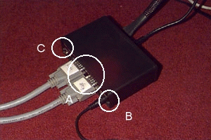
The back of the helmet control box is shown in Figure 2.

The main connectors on the back are the two video sources (label A). The cables for these are labelled "left" and "right" so that it is easy to identify the cable to plug into the Onyx (see below). Please make sure that the cables are reconnected properly if you disconnect them in order to make a video. There are a pair of dip switches on the back of the control box (label C). The left of these controls switches between mono and stereo display. In mono mode the left eye video signal is sent to both eyes. The cable B is the power cable to the transformer.

The video connectors have been removed in this picture, but the lower port named channel 1 should be permanently connected to the left eye on the helmet control box. If running in mono mode, channel 0 should be connected to the monitor, in stereo mode, channel 0 should be connected to the right eye.

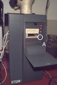
The power switch is the obvious red-button on the front. The button labelled A is the tracker reset. It should be pressed before every attempt to run immersive software. The reset cycle takes 9 seconds, so pause before running the software. The tracker cables can be seen emerging front the left of the front panel. Figure 5 shows the front of the PV100VTX with the front panel removed.

It is important to remember that the fastrak devices must not be detached when the power is on. The two receivers are plugged into the left hand sockets (A) (head to the top-left, hand to the bottom-left as indicated by labels next to the sockets). The transmitter is plugged into the rightmost socket (B). The fastrak has several configuration options, see the manual. Note that the fastrak in the PV100VTX has been customised by Division, the "Receiver selector" switch, has been resoldered inside the case of the PV100, so the machine must be dismantled to change the number of trackers supported (the new internal dip-switches are labelled back to front and upside down).
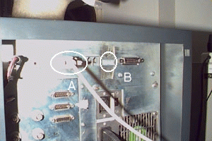
Figure 6 shows the back of the PV100VTX (the VPX is similar).

Indicated are the serial connection to the Onyx (A), and the communication configuration dip switches (B). The switches are set up to report at 38400 baud, and this should not be changed.
The tracker is connected to the Onyx via the connector labelled C in Figure 3. This is named /dev/ttyd2 on the Onyx itself.

The connector to the 3D Mouse is indicated by label C. For the moment this is a bare connector, which can be joined in two orientations. Power comes from a transformer to A. The light B should come on when the power is connected. The light will go off after the configuration has been set in software (see below). Every time a data packet is sent, the light will then flash. The button device is connected to the port labell /dev/ttyd3 labelled B in Figure 3.

This means it is more simple to connect 4 trackers to this box than that on the PV100 VTX. Label B shows the extra two receiver connections.
The two important combinations are:
Original code and source for all these scripts can be found as part of the Dive support for the immersive system. See Dive Immersive page.

At the moment, the 3D mouse to button box cable needs re-shielding and a proper connector. Both the serial cables on the Onyx need replacing - in particular the one on the button box since we needa break out box to make it work. We need a video splitter on the monitor/right eye output.